PCBs Arrived from OSH Park
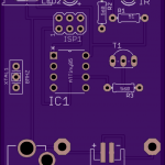
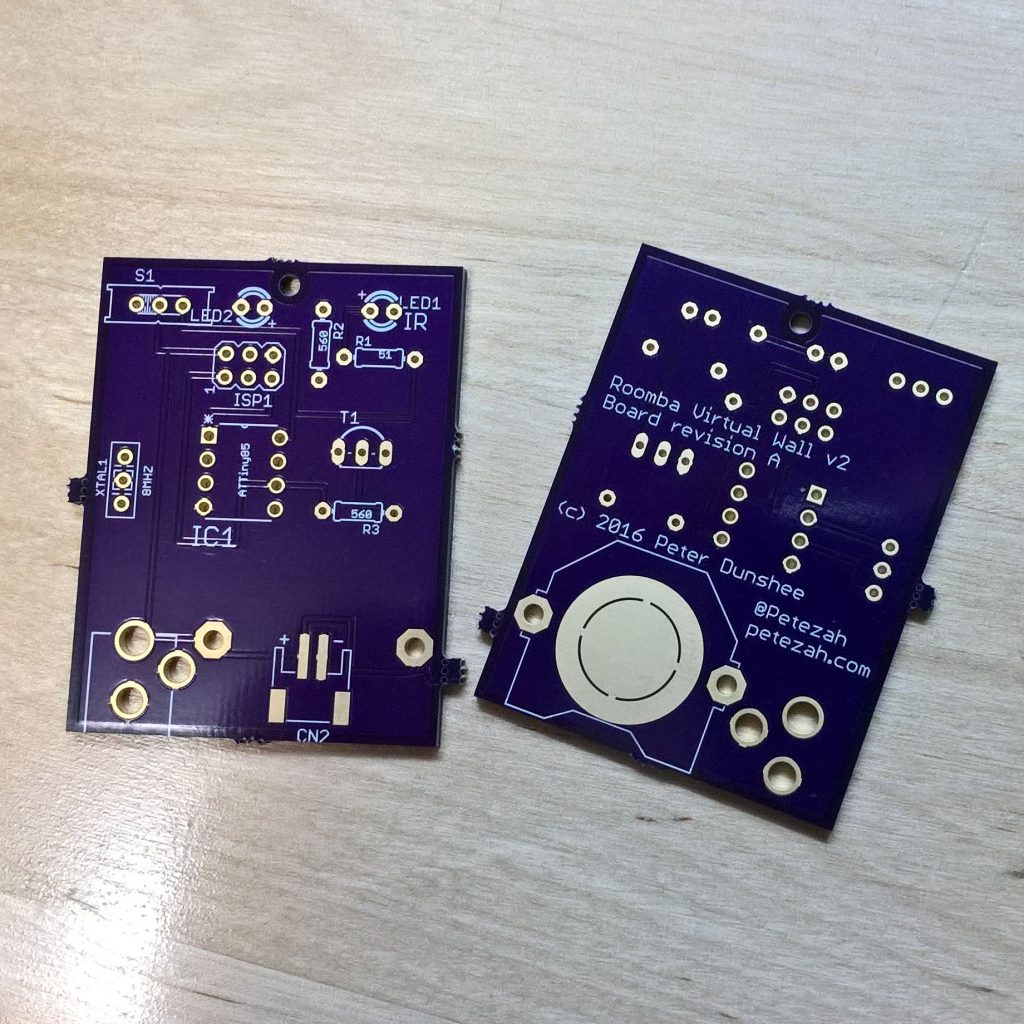
 Based on the breadboard prototype, I designed a PCB for a real prototype and sent it off to OSH Park to be fabricated. I’m not quite sure what kind of power supply I’ll want for this yet; therefore, I designed three options into the first revision—a CR2032 coin cell clip, a 2mm barrel jack, and a 2 connector surface mount JST connector. I’ll start with the coin cell and see how far that gets me, and will proceed from there. Surely one of those will yield, at the very least, useful data.
Current board designs are on the GitHub project page. I’m also sharing them on OSH Park, and interested makers can order the board with the handy button below.![]()
 Continuing the experiment from last time, next up I needed to build a more real prototype using the actual ATTiny85 chip. I wanted the firmware to be buildable outside of the Arduino environment, ideally inside of Atmel Studio as well as using a Makefile on the command line. This involved stripping the code down to bare AVR register manipulation. I initially wanted to just use the built-in 8 Mhz oscillator on the chip, but based on a clue from the TV-Be-Gone Kit project, discovered a bit later, I found the reason my new prototype was not working was because the internal oscillator is not quite stable enough. So I used an 8 Mhz ceramic resonator. The TV-Be-Gone project’s help also allowed me to strip the complicated timing code from my project. The result is now on GitHub.
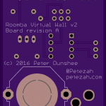
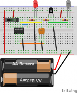 There are a couple other additions here versus the original breadboard prototype. One is the addition of a slide switch from the positive bus to the VCC pin on the ATTiny85, and the other is an actual dedicated power supply attached to the power bus. Astute observers will note that this is not the same as the photo above; that is merely because the LiPoly battery is just what I happen to have on hand currently. I put the AA battery holder into the drawing because those are cheaper and more readily available.
This prototype was also successful. When tested on the Roomba, the vacuum turns around at the proper time, as expected. Now I intend to build a new prototype on an actual PCB.
Shortly after we bought our Roomba, it became clear that the virtual wall idea is truly useful. However, there are a few flaws with the one that comes with the vacuum: the device is rather large, it doesn’t sit in a very stable way on carpet, and it is generally too easy to move—mainly because of the prior two issues. Therefore I immediately began thinking about building an alternate version of the device. It would have two main features:
These made me think of the ATTiny85. It is both small and cheap, and comes in a DIP package that would be easy to solder. These days, I like to test my initial ideas out on the Adafruit Trinket, and I build my first prototype with that. The code is on GitHub, and the assembly pictures are below.
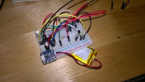
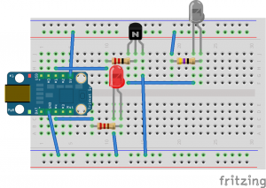 This has no dedicated power supply because it relies on the +5V coming from the Trinket. Also notice that there is an IR receiver and a few more jumpers on the actual breadboard in the photo. That is from an additional test sketch that I was running on a separate MCU board to test the actual transmissions that were coming off of the IR LED.
 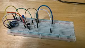 Testing this circuit on the Roomba proved successful. Initially, I had too large of a resistor on my IR LED, and the signal was too weak. But with the 51 ohm resistor, it has a range of a little over two feet, which is more than enough.
Next up was building a more real prototype using the actual ATTiny85 chip. I’ll talk about that in my next entry.
We have a bunch of spots around our house where the previous owner had planted something, and for one reason or another, the plants are now dead. Not wanting to make the same mistake, I decided to make something useful out of the little IoT kit that I received at Build. It has been in a sort of planning phase for a while now (mostly while we wait for Winter to defrost); so I already had a few more of the components on hand and on order.
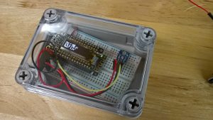 After testing out a simple photo resistor that I already had, I opted for the log-scale analog light sensor sold on Adafruit. Rather than forcing me to set the circuit up for a specific light range, it allows the device to be sensitive from 2-3 lux all the way up to 55000—direct sunlight. I also went for a waterproof enclosure, since it will sit outside for long periods of time unattended, and I don’t want it to get ruined in the elements. (The enclosure works beautifully, by the way—it rained for the first three days I had it outside, and I had no issues.)
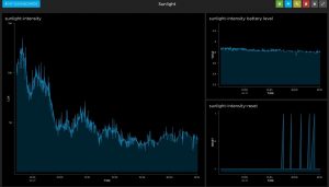 I went with Adafruit.Io for my data logging, and initial data seemed promising. I also decided to log the battery output voltage to try to monitor the life of the device, as well as to log a data point whenever the device had to reset itself. I setup the watchdog timer, because initial versions appeared to lock up. Plus, resetting manually is kind of a pain when you’re using a waterproof enclosure.
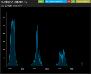 After a little iterating, it seems like it is giving me useful data. Here you can see the device in three different areas over the course of three days—the first area getting full sun for maybe two to three hours, and the third not really getting much sun at all. Eventually I may clean my code up and release it, in case anyone else finds this useful.