I hI’ve been working for a while now on a new project for an actual customer. It is a pager device designed to operate on an existing Wi-Fi infrastructure. Naturally, it has a few other requirements that are a prerequisite for something like this: a battery and a vibration motor, among other things. Then, to complicate things further, I decided to add an ATECC508A crypto IC for security. That particular part was inspired by Mongoose OS, who Tweeted at me at one point while I was collecting the parts I needed. At some point, at least, I want to experiment with their OS, and I may as well use my own board to take it for a test drive.
Stencils for fun and profit
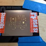
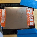
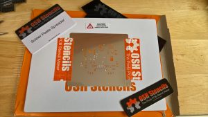 Knowing my current prototype board has roughly 40 part placements on it, and since I would be assembling the first ones myself, I decided to spring for a stencil in order to keep myself sane. Once I finished the board layout, I sent for a stainless steel stencil from OSH Stencils. They exceeded my expectations with an absolutely gorgeous stencil.
Now, assembling the pager
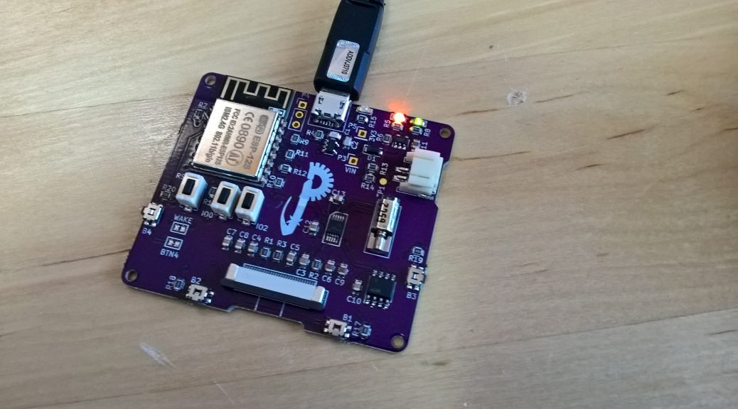
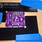
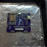
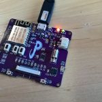
Once I had the boards and all the parts, it was time to assemble a test board. It took a little over an hour to set up the jig, spread the solder paste, and tweeze each part into place. I did the placement with the board on the skillet so that I would not have to move it again and risk jostling the parts from their positions. Once I finished placement, I transferred my skillet to the stovetop for reflow.
It’s alive–sort of
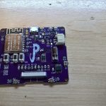
As most experimenting goes, though, there are some hiccups. On power-up, I found that most everything on the pager worked as expected–the ESP8266 module worked, and was programmable; the battery charge circuit worked (more on that later); and the motor driver and crypto chip were visible on the I2C bus. There were some mistakes, however.
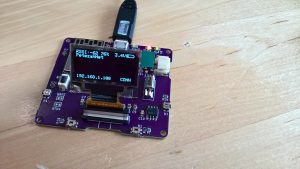
Right away (before testing), I realized I had gotten the battery polarity wrong on the connector. I made a little test jig to test the charge circuit in spite of that. But also, the display failed to do anything, and the connector got really hot when I powered on the device. It was at that point, I discovered that I had misinterpreted the datasheet, and I had reversed the pins for the connector. That discovered, I soldered a second connector on top of the first one, at a right angle and with the pins exactly reversed. Once I did that, I found that the OLED circuit worked as expected. Now I could just rework a couple bits of the circuit, and order new boards. All in all, I considered the experiment a success.
Your mileage may vary
If you feel like it at this point, you can order one of my revision “A” boards at the link below with the caveats described above. I plan to do a write-up when revision “B” is ready, however.![]()