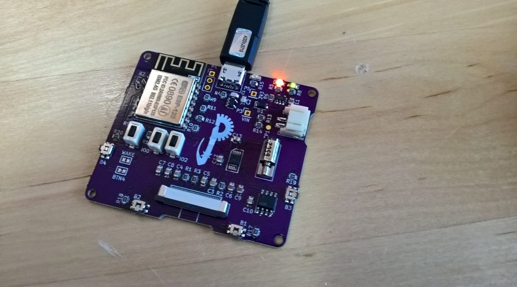
I hI’ve been working for a while now on a new project for an actual customer. It is a pager device designed to operate on an existing Wi-Fi infrastructure. Naturally, it has a few other requirements that are a prerequisite for something like this: a battery and a vibration motor, among other things. Then, to complicate things further, I decided to add an ATECC508A crypto IC for security. That particular part was inspired by Mongoose OS, who Tweeted at me at one point while I was collecting the parts I needed. At some point, at least, I want to experiment with their OS, and I may as well use my own board to take it for a test drive. Continue reading A Wi-Fi pager–or, Experimenting with New Parts
Category Archives: Embedded
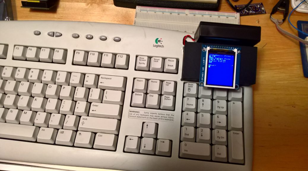
Assembling the keyboard toy (or: shipping an unfinished product)
After much iteration on the firmware for the keyboard, I decided on finally assembling the device, in spite of not being completely finished. It will continue to be a work-in-progress, but I need to move on to other projects for now. Once I finish some other projects, I’ll come back to this one.
Continue reading Assembling the keyboard toy (or: shipping an unfinished product)
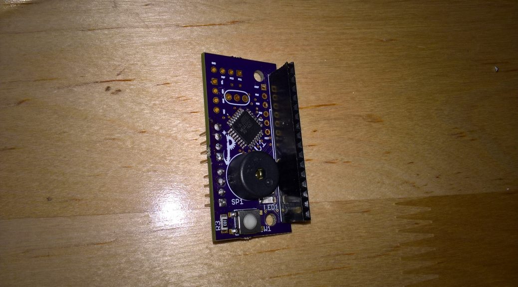
Reflow soldering: further experiments and observations
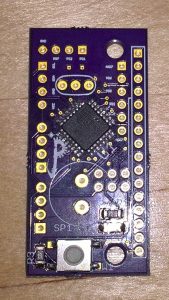
Emboldened by my past success with the Roomba revision D boards, I decided to incorporate this new knowledge of reflow into the next revision for the keyboard toy. A few things needed to change with this design. First, I never did find a good way to incorporate the port expander into the final design; so out it went. Second, the wire harness proved much too cumbersome–I would use a simple female header instead for the TFT. Third, to save space, I would use the TQFP-32 package for the ATMega328p. Continue reading Reflow soldering: further experiments and observations
Adventures in SMD
While trying to iron out the last details of the keyboard project, I decided to try my hand at a surface mounted design, and ordered some tiny ATTiny45 chips (TSSOP) while ordering some other things. What caused me to take the plunge was that I realized I actually had all the tools I needed already. Reading up on the topic lead me to the conclusion that the most economical way to do the soldering would be to use a skillet or hot plate; and rather than buy another tool, I wanted to attempt to use a cast iron skillet that I already had. My thought was that cast iron heats very slowly and evenly and would have many of the same benefits, in that respect, or some other options I had read about. Continue reading Adventures in SMD
Roomba board, revision “B”
It’s been a while since I’ve written an update to this project, and there have been a number of developments; so it’s about time. I now have a couple revision “B” boards deployed, also with new, more efficient firmware. I haven’t been running the new boards or the new firmware long enough to really tell how much better they are performing, but it ought to be significant. The big power draws are the LEDs, and they are now enabled far less frequently. For the interested, all the new info is up on my GitHub project page. Although, I was pretty sure I updated the ReadMe, but I’m not seeing the changes at the moment. I’ll have to check and make sure I committed them. But really, the important changes are:
- I have, since rev “A”, build a new AVR ISP tool that I use to program my boards. (GitHub or OSH Park) This makes programming the rev B board much easier, since you don’t actually solder the ISP header onto the rev B board; you just “wedge” the pins into the vias during programming.
- … I guess that was it. I thought there was more than one, but I can’t remember it now. Perhaps it was unimportant.
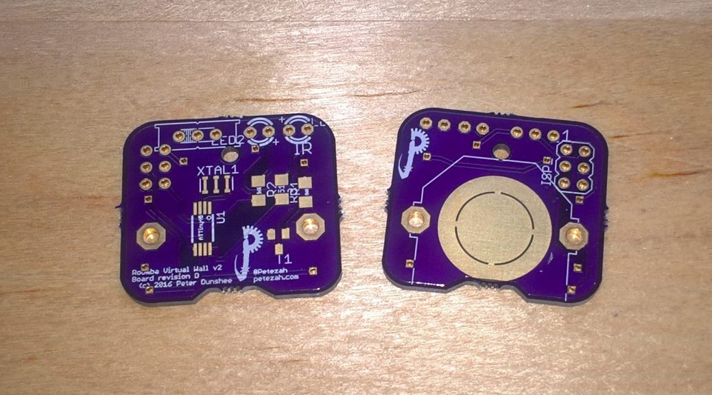
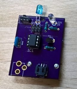
Next up, I have a revision “D” board coming which uses the SSOP8 package of the ATTiny45 and is smaller, even, than this board. For those keeping score, yes, there is a “C” board–it uses a SOIC8 ATTiny, and I realized, before ordering the board, that it was the wrong footprint for the part I had ordered. But I liked the design, so I kept it and made revision “D” instead.
Updates on the Roomba project
I noticed yesterday that I had a mention on the OSH Park blog. Besides that, I have found through my testing this month that the device can run for about 30 hours on a CR2035 battery. In normal use, this amounts to almost a full month of usage, which isn’t bad, but I’m going to experiment to see if I can get it better. I’ll start by tweaking the firmware to see if I can get it to be a bit sleepier and still work. Stay tuned.
Two new PCBs
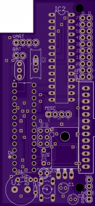
I finally wrapped up layout on the first hardware revision for the AVR keyboard toy project and ordered a small batch of them from OSH Park.
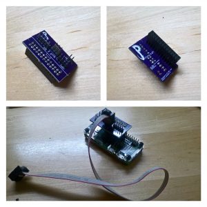
Along the way, I decided to quickly finish up my Raspberry Pi ISP tool so that I can use that to program the microcontrollers on these boards when they are ready, because currently, it is not so convenient to do that. The curious can also find this board shared on OSH Park.
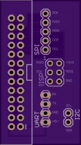
Besides the ISP header that allows you to use a standard 6-pin IDC cable to program your boards, it has a few other goodies too, since I thought they might come in handy: UART, I2C and the full SPI bus are all also there.
The firmware is not quite finished for the keyboard toy, but at least I can start building the device now once the boards arrive.
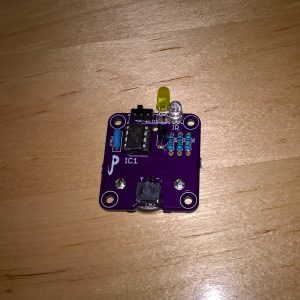
Finished Revision “A” Virtual Wall
 I’ve now built two boards with my OSH Park PCBs, and have been running them successfully for four days now. At the moment, it’s an experiment to see how long the batteries will last in production. If it’s acceptable, I’ll think about making a new, smaller board with only the necessary parts. I’m also already thinking about ways I could possibly improve the device. But I may just leave it as-is, since it is a simple, and effective solution.
Here are the current instructions (also available on GitHub):
Building
Prerequisites for “happy path”:
- Raspberry Pi configured with BCM SPI enabled
- AVR-GCC installed
- Easiest way to get this is ‘sudo apt-get install arduino’
- Jumpers to wire SPI bus of Raspberry Pi to the ISP pins on the finished board
Steps
Hardware
- Order a board based on the files in https://github.com/Petezah/roomba_wall_v2/tree/master/hardware/roomba_wall_v2
- Alternately, order one directly from OSH Park here: https://oshpark.com/shared_projects/zFWYzgg5
- Purchase parts from Mouser electronics using the current BOM
- Use the ones with “mouser” in their filenames
- NB: The DC jack in the current BOM is incorrect
- Assemble the board–parts are all marked on the silkscreen
Firmware
- Hook up the ISP pins on the assembled board to your Raspberry PI as follows:
- ISP Pin 1 –> Raspberry Pi Pin 21 (MISO)
- ISP Pin 2 –> Raspberry Pi Pin 17 (3.3V)
- ISP Pin 3 –> Raspberry Pi Pin 23 (SCK)
- ISP Pin 4 –> Raspberry Pi Pin 19 (MOSI)
- ISP Pin 5 –> Raspberry Pi Pin 15 (GPIO22)
- ISP Pin 6 –> Raspberry Pi Pin 25 (GND)
- Execute the following on the Raspberry Pi command line
- cd firmware
- make fuse
- make install
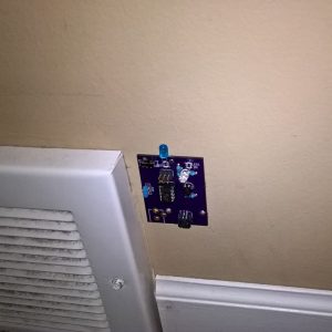 This is a picture of the intended use. The current PCB has a drill-hole in the top-center which fits a tiny finishing nail or wire brad perfectly. Pre-nail the wire brad, and slide it through the hole in the board and into the wall (or whatever surface you are using). Slide the switch to the “on” position when you use your Roomba, and back to “off” when finished, to preserve battery life.
PCBs Arrived from OSH Park
First Revision PCB for the Roomba Virtual Wall
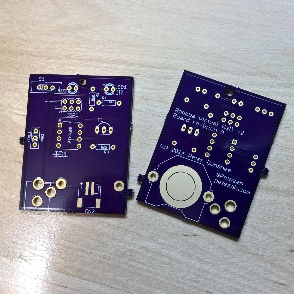
 Based on the breadboard prototype, I designed a PCB for a real prototype and sent it off to OSH Park to be fabricated. I’m not quite sure what kind of power supply I’ll want for this yet; therefore, I designed three options into the first revision—a CR2032 coin cell clip, a 2mm barrel jack, and a 2 connector surface mount JST connector. I’ll start with the coin cell and see how far that gets me, and will proceed from there. Surely one of those will yield, at the very least, useful data.
Current board designs are on the GitHub project page. I’m also sharing them on OSH Park, and interested makers can order the board with the handy button below.![]()