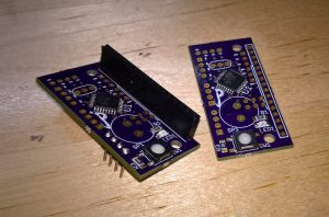
Emboldened by my past success with the Roomba revision D boards, I decided to incorporate this new knowledge of reflow into the next revision for the keyboard toy. A few things needed to change with this design. First, I never did find a good way to incorporate the port expander into the final design; so out it went. Second, the wire harness proved much too cumbersome–I would use a simple female header instead for the TFT. Third, to save space, I would use the TQFP-32 package for the ATMega328p.
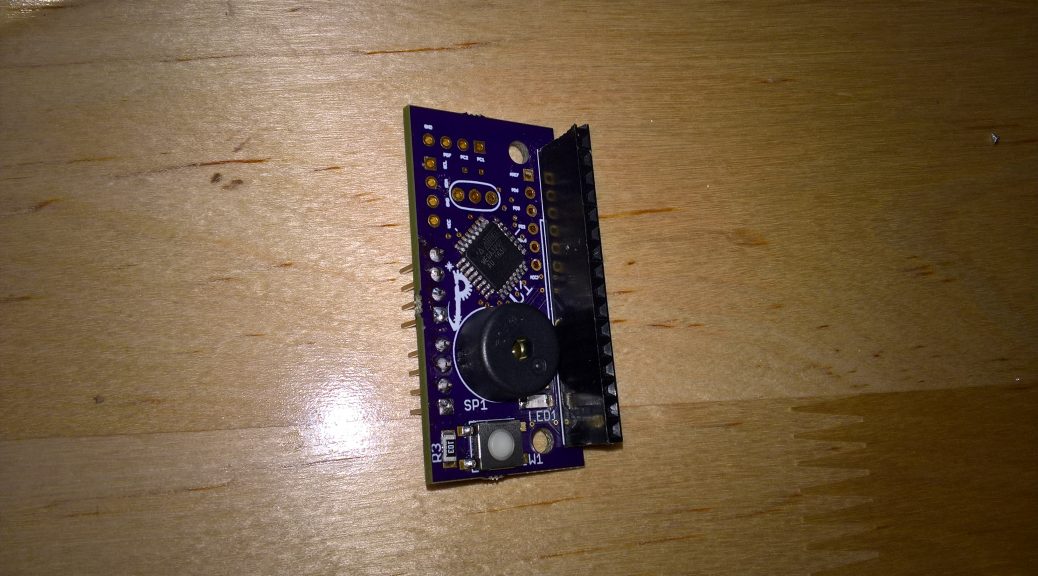
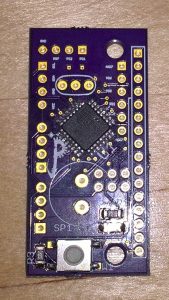
The result was a board that was close to 60% smaller than the first revision boards. Once I received them from OSH Park (much sooner than expected due to being promoted to Super Swift), I began assembly. A couple more observations emerged, which I will now share, in no particular order because they may be equally important.
Reflow observations
First, with solder paste, a little goes a long way.
Different people have stated this before, in multiple ways, but it was not always apparent why. In my case, I assemble without a stencil by squirting paste directly onto the solder pads on the board. It seemed like no matter how careful I was, I always ended up with bridged pins. The third time was the key, however. On the third try, I ended up smearing the paste thinly onto the pads of the TQFP. It was messy, and not at all “in the lines”, but the cooked result ended up with no issues at all. The solder mask took care of the extra paste that was in the wrong place.
Second, bridged pins are actually not that hard to fix.
I never really figured this out in the Roomba boards, but in these boards, I found the working formula. Applying flux from my no-clean flux pen onto the pins, and then heating the solder wick on top of everything sucked the bridges out every time.
The result:
I had three working boards to test with! With the solder jumpers on my boards, I configured a couple of them to suit my current testing and development. And I am now ready to try some bigger chips in my next experiment.
Hi. im loving this project. i find is very attractive that it looks very simple and easy to build. once you have this finished would you be making it open source ? i just wanted to mention that in my personal experience a fan output is a good idea to cool after the reflow or to keep it on to help distribute the heat evenly inside the oven. also a buzzer to alert of the finished reflow also helps
Thanks! It is open source and available on my GitHub repository at https://github.com/Petezah/AVRKeyboardToy. I guess I should make a page for it to make it easier to find. Thanks for the tip on the reflow oven. I actually reflow using a skillet–more specifically, a tiny cast iron skillet for its even heat conductivity. I pull it off the heat when it all hits the melting point for a few seconds, then remove the board with tweezers usually, and set aside to cool.