While trying to iron out the last details of the keyboard project, I decided to try my hand at a surface mounted design, and ordered some tiny ATTiny45 chips (TSSOP) while ordering some other things. What caused me to take the plunge was that I realized I actually had all the tools I needed already. Reading up on the topic lead me to the conclusion that the most economical way to do the soldering would be to use a skillet or hot plate; and rather than buy another tool, I wanted to attempt to use a cast iron skillet that I already had. My thought was that cast iron heats very slowly and evenly and would have many of the same benefits, in that respect, or some other options I had read about.
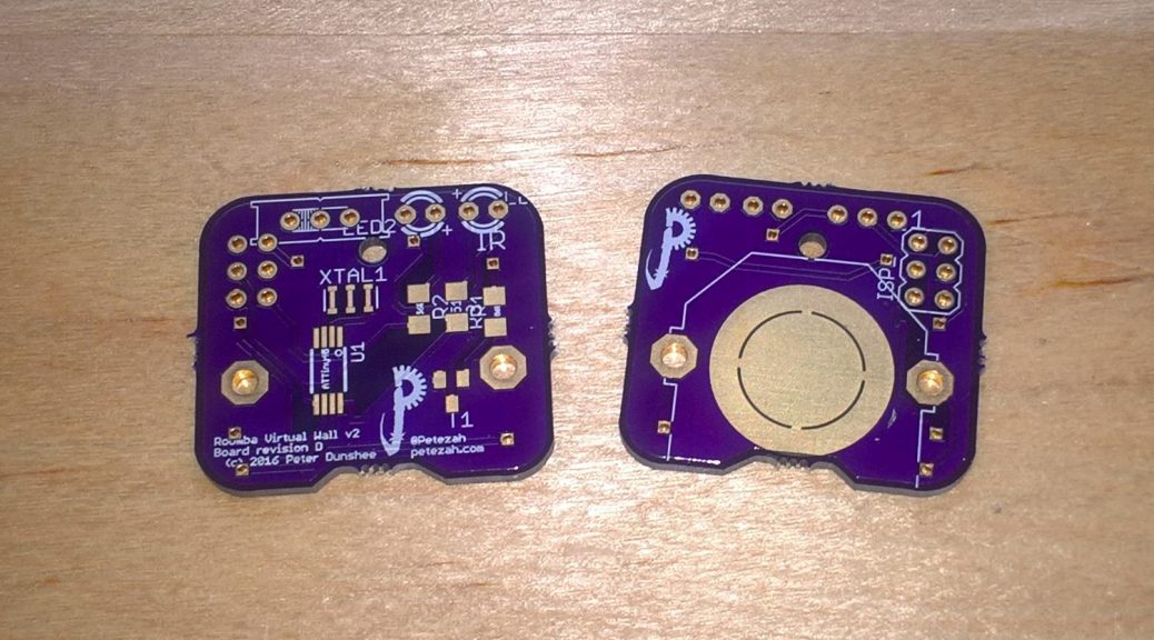
So, after modifying my revision “B” design a couple times, and ensuring that the chips I had ordered fit the new design (they didn’t initially; I accidentally used the SOIC package in the first design), I ordered some new boards. Once they arrived, and I had some free time, I made my first attempt at assembly. To my delight, the cast iron skillet worked beautifully to heat the board for reflow.
The disappointment came when I realized that I had a solder bridge on the chip between pins 1 and 2. I made a sloppy attempt to fix this, and ended up just needing to try again. The second attempt went a little better. I was a bit too liberal with the solder paste on the first, and in the second I resolved to remedy this. Rather than apply a bead across the pads as I had seen some do on some assembly videos, I just applied a small amount over each pad.
This one also ended up with a solder bridge, albeit on a different pair of pins. Rather than try to fix this immediately, I went for a third attempt. The third one had the same problem, although much less pronounced. I decided to try to fix the bridge in a more delicate way than I had before, especially since it seemed pretty insignificant a problem. After heating the pins with my soldering iron, I pulled the errant solder out with my trusty x-acto knife. Then came the test: to see if I could program the board.
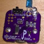
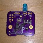
After modifying the makefile for the firmware to build for the ATTiny45 instead of the ATTiny85, I wedged the programming pins into the header vias and initiated install. Success! Burning fuses was also a success. I assembled the rest of the board, inserted a coin cell battery, and tested again. Nothing. Then I tried the programming process again. It succeeded still, and this time, the status LED was blinking, indicating that it was working. Okay. Try the battery again. Still nothing. Weird.
I repeated the same fix steps for the second board, just for fun, and had a different problem: the programming seemed to work, but during verify, the programmer was returning all zeros. Strange. So, after all that, I decided to shelve it until I could think about it more and get back to it.
Later on, due to some unforeseen wear-and-tear on my deployed Roomba boards, I had a thought to do a fully surface mount design, replacing my through-hole LEDs with surface mount parts to see if it would be more durable. During this design process–actually late in the process–I happened to notice that one of the pins on the microcontroller didn’t seem to be connected to anything on the board. That seemed odd. I checked the schematic, and it looked okay. Looking closer, I discovered that the net from the ground pin seemed to be connected to the ground net, but actually was not! During one of my part-swapping processes, it had gotten disconnected, and since it looked connected, I hadn’t touched it again.
I wondered if the other boards had the same problem. Inspecting the board files revealed that, yes, they too had the issue. I attempted a fix. Since I had designed my boards with a copper fill for the ground, a ground plane was actually very close to the ground pin of the IC already. I took my x-acto knife, cut through the solder mask near the pin, and used my iron to lay down a little bridge of solder from the ground plane to the pin. After the board was cool, I plugged the battery in again and it worked! Excited with my newly working board, I tried the same fix on the other not-quite-working board and had the same success.
Lesson learned: inspect the boards a bit more closely before sending them off to the fab.
Thank you for sharing all these details. Really enjoy reading it.
Hey Peter,
Your project has inspired me to extend your work somewhat.
I’m working on incorporating an RTC into the project to automate the On/Off functionality (to sync with the roomba schedule and improve battery life).
Is this something you have already considered? The ATtiny 814 (and similar SMD chips in the ATtiny family) have inbuilt RTCs. If the external resonator is exchanged with a 32.X crystal, it might be possible.
Let me know what you think, or if this is something you’ve already decided against incorporating into your own project.
Hi Austen,
Using an RTC to time it is definitely an interesting idea. I don’t think it will work with the ATtiny built-in RTC though: the IR transmitter needs to send at 48kHz, but your clock crystal is going to be oscillating at 32.* kHz. From that, it should not be possible to generate the correct frequency with the slower crystal. If you can get away with using a multiple of slower clock though (haven’t looked into this personally), you may be able to use a divider to get to the right frequency in both cases.
I’m guessing though, that you may just need another part on your BOM for the RTC. It’s still an interesting idea though. Regarding battery life, currently the way I use the device is I just manually switch it on before the Roomba comes out, and switch it off afterward. It works for me, because I often have to clear other kinds of debris at the same time anyway, and I just do it all at once. 🙂 For a vNext of the firmware though (also requiring a vNext board), I had thought to allow a person to set the amount of time it would be on with a button push (like, 1 hour per push or something). Just another idea. Thanks for reading and sharing! I’d love to see if you come up with something along this line of thought.
Hi Austen,
Sorry! I was just looking at the datasheet from the 814/817/etc family, and I realized I was misinformed before. From the block diagram of the chip, it appears as if you can select the RTC clock separately from the main clock, such that you could run the main program at 16Mhz and the RTC at 32.x khz. The only problem I can see with that, is I couldn’t get a very good, phase correct 48khz PWM when I used the internal RC clock. Only when I switched to the external 8 Mhz resonator did I get a solid signal to trigger the Roomba. Anyway, I hope that helps.