I finally wrapped up layout on the first hardware revision for the AVR keyboard toy project and ordered a small batch of them from OSH Park.
Along the way, I decided to quickly finish up my Raspberry Pi ISP tool so that I can use that to program the microcontrollers on these boards when they are ready, because currently, it is not so convenient to do that. The curious can also find this board shared on OSH Park.
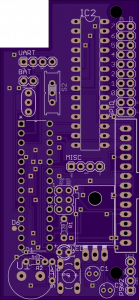
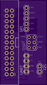
Raspberry Pi ISP tool: an AVR ISP helper and GPIO breakout board.
Besides the ISP header that allows you to use a standard 6-pin IDC cable to program your boards, it has a few other goodies too, since I thought they might come in handy: UART, I2C and the full SPI bus are all also there.
The firmware is not quite finished for the keyboard toy, but at least I can start building the device now once the boards arrive.
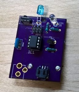
I’ve now built two boards with my OSH Park PCBs, and have been running them successfully for four days now. At the moment, it’s an experiment to see how long the batteries will last in production. If it’s acceptable, I’ll think about making a new, smaller board with only the necessary parts. I’m also already thinking about ways I could possibly improve the device. But I may just leave it as-is, since it is a simple, and effective solution.
Assemble the board–parts are all marked on the silkscreen
Firmware
Hook up the ISP pins on the assembled board to your Raspberry PI as follows:
ISP Pin 1 –> Raspberry Pi Pin 21 (MISO)
ISP Pin 2 –> Raspberry Pi Pin 17 (3.3V)
ISP Pin 3 –> Raspberry Pi Pin 23 (SCK)
ISP Pin 4 –> Raspberry Pi Pin 19 (MOSI)
ISP Pin 5 –> Raspberry Pi Pin 15 (GPIO22)
ISP Pin 6 –> Raspberry Pi Pin 25 (GND)
Execute the following on the Raspberry Pi command line
cd firmware
make fuse
make install
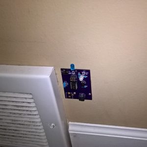
This is a picture of the intended use. The current PCB has a drill-hole in the top-center which fits a tiny finishing nail or wire brad perfectly. Pre-nail the wire brad, and slide it through the hole in the board and into the wall (or whatever surface you are using). Slide the switch to the “on” position when you use your Roomba, and back to “off” when finished, to preserve battery life.