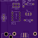
 Based on the breadboard prototype, I designed a PCB for a real prototype and sent it off to OSH Park to be fabricated. I’m not quite sure what kind of power supply I’ll want for this yet; therefore, I designed three options into the first revision—a CR2032 coin cell clip, a 2mm barrel jack, and a 2 connector surface mount JST connector. I’ll start with the coin cell and see how far that gets me, and will proceed from there. Surely one of those will yield, at the very least, useful data.
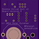
Current board designs are on the GitHub project page. I’m also sharing them on OSH Park, and interested makers can order the board with the handy button below.![]()
First-generation models must be told the room size, while second- and third-generation models estimate room size by measuring the longest straight-line run they can perform without bumping into an object.