 Continuing the experiment from last time, next up I needed to build a more real prototype using the actual ATTiny85 chip. I wanted the firmware to be buildable outside of the Arduino environment, ideally inside of Atmel Studio as well as using a Makefile on the command line. This involved stripping the code down to bare AVR register manipulation. I initially wanted to just use the built-in 8 Mhz oscillator on the chip, but based on a clue from the TV-Be-Gone Kit project, discovered a bit later, I found the reason my new prototype was not working was because the internal oscillator is not quite stable enough. So I used an 8 Mhz ceramic resonator. The TV-Be-Gone project’s help also allowed me to strip the complicated timing code from my project. The result is now on GitHub.
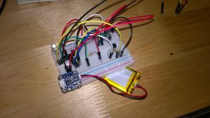
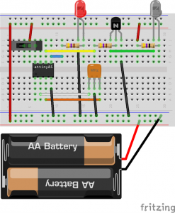 There are a couple other additions here versus the original breadboard prototype. One is the addition of a slide switch from the positive bus to the VCC pin on the ATTiny85, and the other is an actual dedicated power supply attached to the power bus. Astute observers will note that this is not the same as the photo above; that is merely because the LiPoly battery is just what I happen to have on hand currently. I put the AA battery holder into the drawing because those are cheaper and more readily available.
This prototype was also successful. When tested on the Roomba, the vacuum turns around at the proper time, as expected. Now I intend to build a new prototype on an actual PCB.
2 thoughts on “AVR Roomba Virtual Wall Prototype (part 2)”